The life of a modern person is not possible without household appliances, one of them is a refrigerator. Unfortunately, the technology is not eternal and over time it fails. The most common breakdown of the refrigerator is a compressor malfunction. Let's talk about how to replace DIY refrigerator compressor.
The scheme of the refrigerator
The refrigerator consists of:
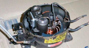
- Compressor, which is inverter and linear type. After starting, the compressor starts to drive freon through the system, thereby cooling the chambers;
- Condenser - tubes located on the rear wall of the refrigerator. Thanks to condenser tubes, the refrigerator does not overheat;
- The evaporator, in which boiling freon and its transition to a gaseous state occurs;
- Valve for thermoregulation, which serves to maintain a given pressure;
- Refrigerant - freon gas or isobutane, which, circulating through the system, helps cool the entire chamber.
Image 1 - scheme of the refrigerator
The refrigeration system is closed. The compressor draws refrigerant from the evaporator, which in turn enters the condenser at high pressure. In the condenser, the gas is cooled and changes its state of aggregation from gaseous to liquid. The resulting liquid flows down the tubes into the evaporator. Thus, a closed continuous operation is ensured.
Almost all the components of the refrigerator are non-stop. The compressor must be switched on from the temperature sensor signal at the moment when the permissible norm of the temperature sensor is exceeded. After the signal is supplied, the compressor, which is set in motion by the relay, starts to work intensively until the temperature indicators return to normal. Then the motor switches off again.
To replace the compressor with your own hands, you also need to understand the wiring diagram.
Image 2 - Electrical Diagram
Having the necessary knowledge, and having the necessary tools at hand, you can easily determine the cause of the breakdown and fix it yourself.
Figure 3 - current flow diagram
According to the scheme, in working condition, the current passes the following path:
- First, the current passes through the contacts on the thermal relay (1);
- Then it hits the defrost button (2);
- Then he gets on the thermal relay (3);
- Next on the current path is a start-up relay (5);
- The working winding of the motor is at the end of the path (4.1).
If the winding is inoperative, then it will miss the voltage of a large size. The start relay will trip, close the contacts and start the winding. As soon as the temperature reaches the desired value, the contacts of the thermal relay will open, and the engine will stop the motor.
Check compressor operation
In order to understand the working compressor or not, you need to take a multimeter. Before attaching the probes of the multimeter, you must make sure that the motor housing "does not break." Otherwise, it may result in electric shock. If everything is in order, you can apply the multimeter probes to each contact on the case in turn. The mechanism is serviceable in the event that the “∞” sign lights up on the multimeter’s display, and if numbers appear, then the fault lies in the winding.
To continue the test, it is necessary to dismantle the casing tightly hiding the compressor. To do this, you have to:
- Disconnect the wiring from the contacts;
- To have a bite of a motor tube connecting it with other details;
Image 4 - motor tube biting
- Unscrew the fixing bolts and remove from the casing;
- Disconnect the relay by unscrewing the screws;
Figure 5 - Disconnecting Relays
- Next, you need to measure the resistance between the contacts;
- Having put the tester probes to the output contacts, normally you should get 25-35 OM (depending on the model of the engine and the refrigerator).
If the value you receive is greater than or less than the norm, the device must be completely replaced.
If the values are normal, then you need to check the performance with a pressure gauge.
To measure the pressure in the compressor, you must:
- Connect a hose with a branch to the discharge fitting;
- Start the engine;
- Measure pressure;
Figure 6 - Compressor Pressure Measurement
In a working mechanism, the pressure gauge should be 6 atm. In this case, you need to quickly turn off the pressure gauge. Due to rapidly increasing pressure, the device may fail. In the idle compressor, the pressure will not exceed 4 bar. Such a compressor must be replaced.
If the pressure is normal and the device does not turn on, there may be a problem in the start relay.
Reasons for the malfunction
The main causes of compressor malfunctions are:
- Lowering or increasing voltage in the power supply network;
- Power surges;
- Disturbed operation of the refrigerator;
- Overheating of the parts of the refrigerator, due to the close proximity of heating devices;
- Independent replacement of defective parts or their repair;
- Damage to the cabinet or condenser when moving the refrigerator.
How to replace the compressor?
Replacing a compressor is a laborious and difficult job, so if you still decide to replace the compressor with your own hands, you should stock up not only with the right tool, and not too much patience.
Let's consider the principle of compressor replacement step by step.
Step One - Preparing the Tool
To replace the compressor yourself, stock up on:
- Gas burner (ideally, it should be oxygen-propane);
- Pliers;
- Storage for refrigerant;
- Valves for piercing and selection.
- portable station for regeneration, refueling and evacuation;
- compact pipe cutter;
- ticks;
- Hansen coupling for tight connection of the compressor with the filling pipe;
- copper pipe 6 mm;
- filter absorber for mounting at the entrance to the capillary tube;
- an alloy of copper with phosphorus (4-9%);
- brown solder as a flux;
- cylinder with freon.
Figure 7 - Compressor Replacement Tool
Since the compressor is located at the bottom of the refrigerator, before replacing the compressor itself, you will have to remove several other components.
Step Two - Freon Release:
- Using pliers, bite the pipes that are connected to the cooling system. Remember - the pipes must be carefully eaten, not cut off. In the process of sawing, shavings are formed, which can get into the capacitor and, moving around the system, can damage the elements;
- Next, run for 5 minutes on the refrigerator. During this time, freon will become a condensate;
- Then connect a valve with a hose attached to the cylinder to the gas line.
- Having opened the valve, bleed all freon. It will take no more than a minute;
- Remove the black box with the wires coming from it - this is the relay block;
- On the search engine, mark the top and bottom for proper installation in the future;
- Bite off the latches and remove it from the crosshead;
- Have a bite of the wiring that leads to the plug
- Unscrew all fasteners and the viewing device;
- Protect all tubes to install a new appliance.
Step Three - Resistance Measurement
To measure the resistance in individual components, you can use either a tester or an ohmmeter, or conventional charging.
If you will use special resistance measuring instruments, you need to apply probes in pairs to the wires. Check the measurements obtained with the table of nominal values for a specific compressor model.
In the case of using a charger, you need to perform the following manipulations:
- Put light bulbs with a power of 6 V minus probes on the body;
- Connect positive probes to the upper leg of the power winding;
- Each of the legs touch the base of the bulb;
Figure 8 - Resistance Measurement
If the unit is in good condition, the lamp should light up when touched on the charger.
Between the feedthrough contacts and the housing, the resistance is checked with a tester. In working condition, the data on the tester will be equal to the infinity sign, in case of a malfunction, the tester will give a digit, usually it is zero.
Fourth step - checking the current strength.
After checking the resistance, it is necessary to measure the current strength. First you need to connect the start relay and turn on the motor. Then hold the tester probe with the contact leading to the instrument.
Instrument readings should be commensurate with engine power. So, if the motor has a power of 120 W, then the current strength should be equal to 1.1 - 1.2 A.
Step Five - Installing a New Compressor
First, you need to fix a working supercharger on the crosshead of the refrigerator unit. Remove all plugs from the tubes that go to the compressor. Check atmospheric pressure.
Remember that compressor depressurization must be done no earlier than 5 minutes before soldering. The connection of the compressor nozzles with the filling, discharge and suction lines should be 6 cm, and a diameter of 6 mm.
Figure 9 - compressor installation
When soldering, pay attention to the direction of the burner fire. It should not be directed inside the nozzles, as plastic elements of the nodes from heating can be deformed or completely melted.
First you need to solder the charge, then remove the excess refrigerant, and then the discharge pipe.
After the soldering process is complete, remove the plugs from the filter dryer, install it on the heat exchanger, after inserting the throttle pipe. Solder the elements and put the Hansen coupling on the filling hose.
The sixth step is to charge the system with refrigerant.
First you need to connect a vacuum to the filling line with a coupling. Then bring the pressure to 65 Pa. Next, make contact switching by attaching a protective relay to the compressor.
After turning on the refrigerator in the network, we fill the system with 40% refrigerant. After checking the device for leaks, unplug it again. After bringing the pressure to a residual norm of 10 Pa, turn on the refrigerator and fill it with freon to the end. We complete the repair by preserving the tubes by clamping, remove the sleeve, and seal the pipe.
How to connect a refrigerator compressor without a relay
In order to connect the compressor directly without a relay, you need to use the scheme:
Figure 10 - Motor connection diagram without relay
Take a two-wire cable with bare contacts on one side and a plug on the other. We put one contact on a common point, the other on the point of the working winding. Connect the contacts of the working and starting windings with a screwdriver, plug the plug into a power outlet. The refrigerator should work. If the start does not occur, there may be a malfunction in the motor or in the cable.
 Pros and Cons of Nou Frost Refrigerators
  Refrigerator next to the stove and oven - can I?
  Is it possible to hang fridge magnets
  How to choose a good two-chamber refrigerator and features of its device
  The water in the refrigerator does not go away and why the water does not freeze in the freezer - what to do

